Wednesday, March 26, 2014

PLC – Theory and Implementation

Definition of PLC – Programmable Logic Controller

Programmable logic controllers, also called programmable controllers or PLCs, are solid-state members of the computer family, using integrated circuits instead of electromechanical devices to implement control functions. They are capable of storing instructions, such as sequencing, timing, counting, arithmetic, data manipulation, and communication, to control industrial machines and processes.
Figure 1-1 illustrates a conceptual diagram of a PLC application.
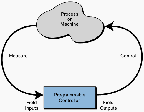
Figure 1-1. PLC conceptual application diagram

Programmable controllers have many definitions. However, PLCs can be thought of in simple terms as industrial computers with specially designed architecture in both their central units (the PLC itself) and their interfacing circuitry to field devices (input/output connections to the real world).

The Conceptual Design Of The PLC

The first programmable controllers were more or less just relay replacers. Their primary function was to perform the sequential operations that were previously implemented with relays. These operations included ON/OFF control of machines and processes that required repetitive operations, such as transfer lines and grinding and boring machines.
However, these programmable controllers were a vast improvement over relays. They were easily installed, used considerably less space and energy, had diagnostic
indicators that aided troubleshooting, and unlike relays, were reusable if a project was scrapped.
Programmable controllers can be considered newcomers when they are compared to their elder predecessors in traditional control equipment technology, such as old hardwired relay systems, analog instrumentation, and other types of early solid-state logic.
Although PLC functions, such as speed of operation, types of interfaces, and data processing capabilities, have improved throughout the years, their specifications still hold to the designers’ original intentions – they are simple to use and maintain.
Title:PLC – Theory and Implementation (L.A. Bryan; E.A. Bryan)
Format:PDF
Size:5.2MB
Pages:1047


PLC - Theory and Implementation

Tuesday, March 25, 2014

HOW TO INSTALL MATE 1.8 IN UBUNTU

MATE 1.8 was released about 3 weeks ago, bringing various refinements and new features such as support for Metacity as window manager, side-by-side window tiling and more, as well as many bug fixes - for more information, see THIS article.  


The official MATE Desktop wiki page doesn't offer Ubuntu installation instructions for the latest MATE Desktop 1.8 (their instructions are for MATE 1.6 - because MATE 1.8 uses a different Ubuntu repository -, at least at the time I'm writing this article), so here's how to install MATE 1.8 in Ubuntu.

Note that the official MATE 1.8 Ubuntu repository only supports Ubuntu 14.04 and 13.10!

MATE Desktop is a GNOME2 fork which lets you use the old GNOME 2 desktop interface and applications but it also allows you to use new applications so for instance, you can use Nautilus 3 with it and so on. Also, MATE can be installed in parallel with GNOME 3, something that wasn't possible with the vanilla GNOME 2.


Install MATE Desktop 1.8 in Ubuntu


Warning: do not use the instructions below if you're using Linux Mint (it might break your installation)!

To add the MATE 1.8 repository and install MATE Desktop 1.8 in Ubuntu 14.04 Trusty Tahr or 13.10 Saucy Salamander, use the following commands:
echo "deb http://repo.mate-desktop.org/archive/1.8/ubuntu $(lsb_release -cs) main" | sudo tee /etc/apt/sources.list.d/mate-desktop.list
wget -qO - http://mirror1.mate-desktop.org/debian/mate-archive-keyring.gpg | sudo apt-key add -
sudo apt-get update
sudo apt-get install mate-core mate-desktop-environment mate-notification-daemon
(MATE 1.6 and 1.8 use different Ubuntu repositories - as you can see in the repo line above, it uses ..."1.8/ubuntu" -, that's why if you follow the instructions on the MATE wiki, you'll get MATE 1.6 in Ubuntu, not the latest MATE Desktop 1.8)

Once all the packages are installed, log out and select MATE from the login screen.

For how to install MATE Desktop in other Linux distributions, see the official MATE wiki.


How to remove MATE 1.8 from Ubuntu


If you've used our instructions to install the latest MATE 1.8 in Ubuntu 14.04 or 13.10, you can completely remove MATE and all the packages installed from its repository by using the following command:
sudo apt-get remove atril atril-common caja caja-common engrampa engrampa-common eom eom-common gir1.2-mate-panel libatril libcaja-extension1 libmarco-private0 libmate-desktop-2-17 libmate-menu2 libmate-panel-applet4-1 libmatekbd-common libmatekbd4 libmateweather-common libmateweather1 marco marco-common mate-applets mate-applets-common mate-backgrounds mate-calc mate-calc-common mate-control-center mate-core mate-desktop mate-desktop-common mate-desktop-environment mate-dialogs mate-dialogs-common mate-icon-theme mate-media mate-media-common mate-media-gstreamer mate-menus mate-notification-daemon mate-panel mate-panel-common mate-polkit mate-polkit-common mate-power-manager mate-power-manager-common mate-screensaver mate-screensaver-common mate-session-manager mate-settings-daemon mate-settings-daemon-common mate-settings-daemon-gstreamer mate-system-monitor mate-terminal mate-terminal-common mate-themes mate-utils mate-utils-common pluma pluma-common

To also remove the MATE 1.8 repository, use the command below:
sudo rm /etc/apt/sources.list.d/mate-desktop.list

Monday, March 24, 2014

Linux Kernel Developer

Linux Kernel Developer Panel Preview: Introductions and Projects

Unless you closely follow the Linux kernel mailing list, it can be difficult to keep up with all of the latest kernel features and changes, especially as the pace and scale of development continues to rise. More than 
Jon Corbet LWN Editor
LWN Editor Jonathan Corbet will moderate the Linux kernel developer panel at Collaboration Summit in Napa, March 26-28, 2014.
1,300 developers from more than 200 companies contributed 12,127 patches to the 3.13 Linux kernel, released in January, according to LWN Editor Jon Corbet's latest Linux weather forecast. And Linus Torvalds will soon release the 3.14 kernel, which will contain a whole new set of features and fixes. The Linux kernel developer panel at Collaboration Summit in Napa, Calif. next week is our first opportunity this year to hear directly from Linux kernel developers about which issues and features are top-of-mind for the kernel community now and in the year ahead. Kernel developers Jens Axboe, Matthew Garrett, Mel Gorman, Greg Koah-Hartman, and Dave Chinner will take the stage for a technical discussion moderated by Jon Corbet. Here, the panelists have answered a few of Corbet's preliminary questions to get the conversation started.
Jon Corbet: Who do you work for, why do they support your Linux kernel development, and what do they expect to get back from that investment?
Jens Axboe: I joined Facebook about two months ago. Facebook supports a lot of open source projects, not just the Linux kernel. They built their platform on top of open source technology, so they fully recognize the value in supporting and improving open source projects. They even take it a step further than most with the Open Compute Platform, opening up the hardware side as well. So I think it's safe to say that they are
jens axboe Facebook
Jens Axboe, Facebook.
serious about being open, and it has paid off economically as well. Matthew Garrett: I'm a security developer at Nebula, a company producing a private cloud solution. The Linux kernel is the foundation of our product, and the basis of many of the security technologies that we implement. Working upstream means we benefit from review by experts and avoids the need to spend time updating patches every time we want to move to a new kernel. It's a little more initial effort, in the long term we end up with a better solution and less wasted developer time.
Matthew-Garrett-Nebula
Matthew Garrett, Nebula.
Mel Gorman: I work for in the R&D department within SUSE which is an independent business unit within The Attachmate Group. SUSE is a software and services provider whose principal product is SUSE Linux Enterprise (SLE) which is a GNU/Linux distribution. There are many projects that SUSE contributes to and one of those is the Linux kernel. Among our many internal projects, we develop and support a fork of the kernel with our source trees published publicly. Internal policy is that all feature development is first developed upstream and backported. There are exceptions to this policy but they are rare.
Mel Gorman SUSE
Mel Gorman, SUSE.
Our work with the free software community is what our product and services are based on. We work on the various projects to implement solutions required by our customers, to remain competitive and sometimes because it's just fun. The upstream policy for kernel development ensures that SLE features are widely reviewed and tested by both the company and the community and controls maintenance overhead. For example, in the event a bug is filed against the SLE kernel there is a chance that the same bug was encountered in the mainline kernel which reduces the time required to close the bug. Interoperability is one of the important benefits for our customers using SLE with many additional supporting products such as SUSE Manager. Merging features upstream first avoids introducing incompatibilities with
greg-kroah-hartman
Greg Kroah-Hartman, The Linux Foundation.
other distributions. Greg Kroah-Hartman: The Linux Foundation. Because they are very nice and let me do development on a wide range of kernel subsystems and maintain the stable kernel releases. (In return they get) a constant stream of stable kernel releases.
Corbet: What are you working on right now?
Jens Axboe: Right now I'm focused on blk-mq, the block multiqueue storage model. It was introduced in the 3.13 Linux kernel, but more work still remains. I'm busy improving the performance and extending the driver coverage, so we can hopefully end up with blk-mq being the one true storage interface for block drivers in the kernel.
Matthew Garrett: Yet another iteration of kernel patches to support Secure Boot, integrating TPMs into our security policy, writing a library to allow runtime configuration of server firmware. And trying to make Linux run reasonably on this Mac.
Mel Gorman: The last feature I worked on was Automatic NUMA Balancing but while I do not consider the feature to be 100% complete I'm not developing it further right now. Right now I'm working on stabilizing the latest kernel that will be used for SLE, validating features, identifying any regressions that have been introduced since our last major release and resolving them. In some cases the regressions also exist in the mainline kernel in which case the bug will be fixed for the upstream, openSUSE and SLE kernels.
Greg Kroah-Hartman: I'm reviewing the OPW (Outreach Program for Women) submission patch process (over 400 patches submitted so far), and doing my normal kernel subsystem maintainer duties of merging patches sent to me and responding to questions asked on the mailing lists. I also have some stable kernel releases being tested on my build system before I release that for review by the community.

MODBUS TCP Configuration

This appendix lists the CGR 2010 ESM-specific read-only registers. MODBUS clients use them to communicate with a MODBUS server (i.e., the switch module). There are no writable registers. For configuration information about MODBUS TCP, see “MODBUS TCP Configuration”

System Information Registers

Memory address spaces 0x0800 through 0x0FFF are system information registers. Clients use the 0x03 Read Multiple Registers MODBUS function code. The system-information register mapping is as follows:
 
Table C-1 System Information Registers
Address
# of Registers
Description
R/W
Format
Example/Note for SKU 1
Example/Note for SKU 2
0x0800
64
Product ID
R
Text
“IE9”
“IEA”
0x0840
64
Software image name
R
Text
“grwicdes-
ipservicesk9-m”
“grwicdes-
ipservicesk9-m”
0x0880
64
Software image version
R
Text
“12.2(58)EY”
“12.2(58)EY”
0x08C0
64
Host name
R
Text
“Switch”
“Switch”
0x0900
1
Number of 10/100 Ethernet ports
R
Uint16
0x4
0x8
0x0901
1
Number of Gigabit Ethernet ports
R
Uint16
0x2
0x2
0x0902
1
CPU board temperature (in Celsius)
R
Uint16
Reads temperature on the switch module CPU board.
0x0903
1
Ethernet Switch Module board temperature (in Celsius)
R
Uint16
Reads temperature on the switch module SFP board.

Port Information Registers

The port information registers are documented as follows:
  • Table C-2 below provides the port information register mapping for the CGR 2010 ESM SFP model (GRWIC-D-ES-6S)
  • Table C-3 provides the port information register mapping for the switch’s Copper model (GRWIC-D-ES-2S-8PC)
  • Table C-4 describes how to interpret the port state values for the switch’s SFP model
  • Table C-5 describes how to interpret the port state values for the switch’s Copper model
  • Table C-6 describes the interface-to-LPN mapping for the switch’s SFP model
  • Table C-7 describes the interface-to-LPN mapping for the switch’s Copper model

Port Information Register Mapping for SFP Model (GRWIC-D-ES-6S)

This section provides the port information register mapping for the CGR 2010 ESM SFP model (GRWIC-D-ES-6S).
Memory address spaces 0x1000 through 0x2FFF are interface registers. Clients use the 0x03 Read Multiple Registers MODBUS function code to access the registers.
 
Table C-2 Port Information Registers, SFP Model
Address in Hex
# of Registers
Description
R/W
Format
1000
64
Port 1 name
R
Text
1040
64
Port 2 name
R
Text
1080
64
Port 3 name
R
Text
10C0
64
Port 4 name
R
Text
1100
64
Port 5 name
R
Text
1140
64
Port 6 name
R
Text
1180
1
Port 1 state
R
Uint16
1181
1
Port 2 state
R
Uint16
1182
1
Port 3 state
R
Uint16
1183
1
Port 4 state
R
Uint16
1184
1
Port 5 state
R
Uint16
1185
1
Port 6 state
R
Uint16
Values for 64-Bit Counters
1186
4
Port 1 Statistics – Number of packets received
R
Uint64
118A
4
Port 2 Statistics – Number of packets received
R
Uint64
118E
4
Port 3 Statistics – Number of packets received
R
Uint64
1192
4
Port 4 Statistics – Number of packets received
R
Uint64
1196
4
Port 5 Statistics – Number of packets received
R
Uint64
119A
4
Port 6 Statistics – Number of packets received
R
Uint64
119E
4
Port 1 Statistics – Number of packets sent
R
Uint64
11A2
4
Port 2 Statistics – Number of packets sent
R
Uint64
11A6
4
Port 3 Statistics – Number of packets sent
R
Uint64
11AA
4
Port 4 Statistics – Number of packets sent
R
Uint64
11AE
4
Port 5 Statistics – Number of packets sent
R
Uint64
11B2
4
Port 6 Statistics – Number of packets sent
R
Uint64
11B6
4
Port 1 Statistics – Number of bytes received
R
Uint64
11BA
4
Port 2 Statistics – Number of bytes received
R
Uint64
11BE
4
Port 3 Statistics – Number of bytes received
R
Uint64
11C2
4
Port 4 Statistics – Number of bytes received
R
Uint64
11C6
4
Port 5 Statistics – Number of bytes received
R
Uint64
11CA
4
Port 6 Statistics – Number of bytes received
R
Uint64
11CE
4
Port 1 Statistics – Number of bytes sent
R
Uint64
11D2
4
Port 2 Statistics – Number of bytes sent
R
Uint64
11D6
4
Port 3 Statistics – Number of bytes sent
R
Uint64
11DA
4
Port 4 Statistics – Number of bytes sent
R
Uint64
11DE
4
Port 5 Statistics – Number of bytes sent
R
Uint64
11E2
4
Port 6 Statistics – Number of bytes sent
R
Uint64
Values for 32-Bit Counters
11E6
2
Port 1 Statistics – Number of packets received
R
Uint32
11E8
2
Port 2 Statistics – Number of packets received
R
Uint32
11EA
2
Port 3 Statistics – Number of packets received
R
Uint32
11EC
2
Port 4 Statistics – Number of packets received
R
Uint32
11EE
2
Port 5 Statistics – Number of packets received
R
Uint32
11F0
2
Port 6 Statistics – Number of packets received
R
Uint32
11F2
2
Port 1 Statistics – Number of packets sent
R
Uint32
11F4
2
Port 2 Statistics – Number of packets sent
R
Uint32
11F6
2
Port 3 Statistics – Number of packets sent
R
Uint32
11F8
2
Port 4 Statistics – Number of packets sent
R
Uint32
11FA
2
Port 5 Statistics – Number of packets sent
R
Uint32
11FC
2
Port 6 Statistics – Number of packets sent
R
Uint32
11FE
2
Port 1 Statistics – Number of bytes received
R
Uint32
1200
2
Port 2 Statistics – Number of bytes received
R
Uint32
1202
2
Port 3 Statistics – Number of bytes received
R
Uint32
1204
2
Port 4 Statistics – Number of bytes received
R
Uint32
1206
2
Port 5 Statistics – Number of bytes received
R
Uint32
1208
2
Port 6 Statistics – Number of bytes received
R
Uint32
120A
2
Port 1 Statistics – Number of bytes sent
R
Uint32
120C
2
Port 2 Statistics – Number of bytes sent
R
Uint32
120E
2
Port 3 Statistics – Number of bytes sent
R
Uint32
1210
2
Port 4 Statistics – Number of bytes sent
R
Uint32
1212
2
Port 5 Statistics – Number of bytes sent
R
Uint32
1214
2
Port 6 Statistics – Number of bytes sent
R
Uint32

Port Information Register Mapping for Copper Model (GRWIC-D-ES-2S-8PC)

This section provides the port information register mapping for the CGR 2010 ESM Copper model (GRWIC-D-ES-2S-8PC).
Memory address spaces 0x1000 through 0x2FFF are interface registers. Clients use the 0x03 Read Multiple Registers MODBUS function code to access the registers.
 
Table C-3 Port Information Registers, Copper Model
Address in Hex
# of Registers
Description
R/W
Format
1000
64
Port 1 name
R
Text
1040
64
Port 2 name
R
Text
1080
64
Port 3 name
R
Text
10C0
64
Port 4 name
R
Text
1100
64
Port 5 name
R
Text
1140
64
Port 6 name
R
Text
1180
64
Port 7 name
R
Text
11C0
64
Port 8 name
R
Text
1200
64
Port 9 name
R
Text
1240
64
Port 10 name
R
Text
1280
1
Port 1 state
R
Uint16
1281
1
Port 2 state
R
Uint16
1282
1
Port 3 state
R
Uint16
1283
1
Port 4 state
R
Uint16
1284
1
Port 5 state
R
Uint16
1285
1
Port 6 state
R
Uint16
1286
1
Port 7 state
R
Uint16
1287
1
Port 8 state
R
Uint16
1288
1
Port 9 state
R
Uint16
1289
1
Port 10 state
R
Uint16
Values for 64-Bit Counters
128A
4
Port 1 Statistics – Number of packets received
R
Uint64
128E
4
Port 2 Statistics – Number of packets received
R
Uint64
1292
4
Port 3 Statistics – Number of packets received
R
Uint64
1296
4
Port 4 Statistics – Number of packets received
R
Uint64
129A
4
Port 5 Statistics – Number of packets received
R
Uint64
129E
4
Port 6 Statistics – Number of packets received
R
Uint64
12A2
4
Port 7 Statistics – Number of packets received
R
Uint64
12A6
4
Port 8 Statistics – Number of packets received
R
Uint64
12AA
4
Port 9 Statistics – Number of packets received
R
Uint64
12AE
4
Port 10 Statistics – Number of packets received
R
Uint64
12B2
4
Port 1 Statistics – Number of packets sent
R
Uint64
12B6
4
Port 2 Statistics – Number of packets sent
R
Uint64
12BA
4
Port 3 Statistics – Number of packets sent
R
Uint64
12BE
4
Port 4 Statistics – Number of packets sent
R
Uint64
12C2
4
Port 5 Statistics – Number of packets sent
R
Uint64
12C6
4
Port 6 Statistics – Number of packets sent
R
Uint64
12CA
4
Port 7 Statistics – Number of packets sent
R
Uint64
12CE
4
Port 8 Statistics – Number of packets sent
R
Uint64
12D2
4
Port 9 Statistics – Number of packets sent
R
Uint64
12D6
4
Port 10 Statistics – Number of packets sent
R
Uint64
12DA
4
Port 1 Statistics – Number of bytes received
R
Uint64
12DE
4
Port 2 Statistics – Number of bytes received
R
Uint64
12E2
4
Port 3 Statistics – Number of bytes received
R
Uint64
12E6
4
Port 4 Statistics – Number of bytes received
R
Uint64
12EA
4
Port 5 Statistics – Number of bytes received
R
Uint64
12EE
4
Port 6 Statistics – Number of bytes received
R
Uint64
12F2
4
Port 7 Statistics – Number of bytes received
R
Uint64
12F6
4
Port 8 Statistics – Number of bytes received
R
Uint64
12FA
4
Port 9 Statistics – Number of bytes received
R
Uint64
12FE
4
Port 10 Statistics – Number of bytes received
R
Uint64
1302
4
Port 1 Statistics – Number of bytes sent
R
Uint64
1306
4
Port 2 Statistics – Number of bytes sent
R
Uint64
130A
4
Port 3 Statistics – Number of bytes sent
R
Uint64
130E
4
Port 4 Statistics – Number of bytes sent
R
Uint64
1312
4
Port 5 Statistics – Number of bytes sent
R
Uint64
1316
4
Port 6 Statistics – Number of bytes sent
R
Uint64
131A
4
Port 7 Statistics – Number of bytes sent
R
Uint64
131E
4
Port 8 Statistics – Number of bytes sent
R
Uint64
1322
4
Port 9 Statistics – Number of bytes sent
R
Uint64
1326
4
Port 10 Statistics – Number of bytes sent
R
Uint64
Values for 32-Bit Counters
132A
2
Port 1 Statistics – Number of packets received
R
Uint32
132C
2
Port 2 Statistics – Number of packets received
R
Uint32
132E
2
Port 3 Statistics – Number of packets received
R
Uint32
1330
2
Port 4 Statistics – Number of packets received
R
Uint32
1332
2
Port 5 Statistics – Number of packets received
R
Uint32
1334
2
Port 6 Statistics – Number of packets received
R
Uint32
1336
2
Port 7 Statistics – Number of packets received
R
Uint32
1338
2
Port 8 Statistics – Number of packets received
R
Uint32
133A
2
Port 9 Statistics – Number of packets received
R
Uint32
133C
2
Port 10 Statistics – Number of packets received
R
Uint32
133E
2
Port 1 Statistics – Number of packets sent
R
Uint32
1340
2
Port 2 Statistics – Number of packets sent
R
Uint32
1342
2
Port 3 Statistics – Number of packets sent
R
Uint32
1344
2
Port 4 Statistics – Number of packets sent
R
Uint32
1346
2
Port 5 Statistics – Number of packets sent
R
Uint32
1348
2
Port 6 Statistics – Number of packets sent
R
Uint32
134A
2
Port 7 Statistics – Number of packets sent
R
Uint32
134C
2
Port 8 Statistics – Number of packets sent
R
Uint32
134E
2
Port 9 Statistics – Number of packets sent
R
Uint32
1350
2
Port 10 Statistics – Number of packets sent
R
Uint32
1352
2
Port 1 Statistics – Number of bytes received
R
Uint32
1354
2
Port 2 Statistics – Number of bytes received
R
Uint32
1356
2
Port 3 Statistics – Number of bytes received
R
Uint32
1358
2
Port 4 Statistics – Number of bytes received
R
Uint32
135A
2
Port 5 Statistics – Number of bytes received
R
Uint32
135C
2
Port 6 Statistics – Number of bytes received
R
Uint32
135E
2
Port 7 Statistics – Number of bytes received
R
Uint32
1360
2
Port 8 Statistics – Number of bytes received
R
Uint32
1362
2
Port 9 Statistics – Number of bytes received
R
Uint32
1364
2
Port 01 Statistics – Number of bytes received
R
Uint32
1366
2
Port 1 Statistics – Number of bytes sent
R
Uint32
1368
2
Port 2 Statistics – Number of bytes sent
R
Uint32
136A
2
Port 3 Statistics – Number of bytes sent
R
Uint32
136C
2
Port 4 Statistics – Number of bytes sent
R
Uint32
136E
2
Port 5 Statistics – Number of bytes sent
R
Uint32
1370
2
Port 6 Statistics – Number of bytes sent
R
Uint32
1372
2
Port 7 Statistics – Number of bytes sent
R
Uint32
1374
2
Port 8 Statistics – Number of bytes sent
R
Uint32
1376
2
Port 9 Statistics – Number of bytes sent
R
Uint32
1378
2
Port 10 Statistics – Number of bytes sent
R
Uint32

Interpreting the Port State for the Switch Module SFP Model

 
Table C-4 Port Information: Interpreting the Port State for GRWIC-D-6S (SFP Model)
Address
Description
Value
0x1180
to
0x1185
Port 1 state
to
Port 6 state
The upper byte represents the interface state:
  • 0x0: Interface is down
  • 0x1: Interface is going down
  • 0x2: Interface is in the initializing state
  • 0x3: Interface is coming up
  • 0x4: Interface is up and running
  • 0x5: Interface is reset by the user
  • 0x6: Interface is shut down by the user
  • 0x7: Interface is being deleted
The lower byte represents the line protocol state:
  • 0x1: Line protocol state is up
  • 0x0: Line protocol state is down

Interpreting the Port State for the Switch Module Copper Model

 
Table C-5 Port Information: Interpreting the Port State for GRWIC-D-2S-8PC (Copper Model)
Address
Description
Value
0x1280
to
0x1289
Port 1 state
to
Port 6 state
The upper byte represents the interface state:
  • 0x0: Interface is down
  • 0x1: Interface is going down
  • 0x2: Interface is in the initializing state
  • 0x3: Interface is coming up
  • 0x4: Interface is up and running
  • 0x5: Interface is reset by the user
  • 0x6: Interface is shut down by the user
  • 0x7: Interface is being deleted
The lower byte represents the line protocol state:
  • 0x1: Line protocol state is up
  • 0x0: Line protocol state is down

Interface-to-LPN Mapping for the Switch Module SFP Model

 
Table C-6 Interface-to-LPN Mapping for GRWIC-D-6S (SFP Model)
Interface
LPN
Fast Ethernet 0/1
1
Fast Ethernet 0/2
2
Fast Ethernet 0/3
3
Fast Ethernet 0/4
4
Gigabit Ethernet 0/1
13
Gigabit Ethernet 0/2
14

Interface-to-LPN Mapping for the Switch Module Copper Model

 
Table C-7 Interface-to-LPN Mapping for GRWIC-D-2S-8PC (Copper Model)
Interface
LPN
Fast Ethernet 0/1
1
Fast Ethernet 0/2
2
Fast Ethernet 0/3
3
Fast Ethernet 0/4
4
Fast Ethernet 0/5
5
Fast Ethernet 0/6
6
Fast Ethernet 0/7
7
Fast Ethernet 0/8
8
Gigabit Ethernet 0/1
17
Gigabit Ethernet 0/2
18